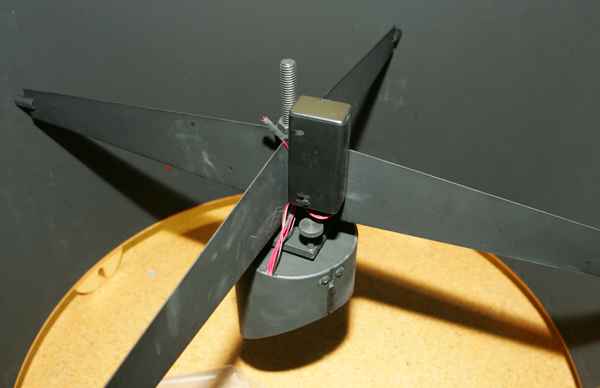
 |
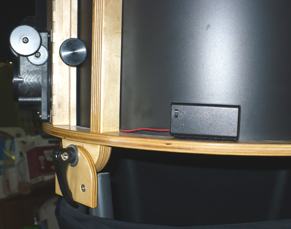
| Battery pack installed behind secondary holder (3.5" and larger secondary) |
The DewGuard is the first temperature controlled heating system designed to help prevent dew formation on a telescope's secondary mirror. The uniform distribution and controlled heating avoids air currents and optical distortion. Newtonian telescopes in the 6" to 36" range can experience condensation on their secondary mirrors. This may be due to the open structure of their upper tube assemblies or severe condensation conditions. The DewGuard will keep it dry.
The DewGuard is attached to the back of the secondary mirror using silicone adhesive or contact cement, available at hardware stores or home centers. Apply a small amount (about 1/32" thick) on the surface of each small square heater. Center the DewGuard on the back of the diagonal, wire end of the circuit board higher, or toward the open tube end of the diagonal, and allow it to cure overnight. You will need to supply the DewGuard with 9 volts DC (9-12V DC is suitable). Attach the pigtail sensor and LED away from the secondary in a convenient location with free air circulation. Do not stuff the sensor into the packing that is supplied with most secondary holders. It is however, OK to stuff the polyfill wadding into the holder and against the DewGuard. The unit is supplied with a 9 volt battery snap connector (DG-1 and 2) or a 9V battery box with switch (DG-3). A 9 volt battery will work for 3-12 hours, depending on the temperature, secondary size and dew conditions. The DewGuard consumes about 0.02 watt at 12V while connected to a power source to operate the temperature sensor, so be sure to disconnect the battery when not in use.
 |
| Battery pack installed behind secondary holder (3.5" and larger secondary) |
Parts supplied:
| 1 | Wire-24" (26 gauge) and 9V plug | 2 | Heat Shrink Tubing | |
| 1 | 9V Battery Case w/ switch | 2 | Wire Mount Screws- #8 x 1/2" | |
| 2 | Wire Mounts (adhesive backed) | 1 | Aluminum Tape- 12" | |
| 1 | Velcro- 2" | 2 | Wire Ties |
This installation kit allows convenient location of the 9V battery case on the lower cage ring or inside the cage. The DewGuard is wired across the spider, giving enough clearance in a small scope where there is not enough room to position the 9V battery behind the secondary holder and the convenience on all telescopes of a switched, easy access battery. This system can be direct wired if dew conditions are so severe that a rechargeable or large capacity 9-12V battery is needed and mounted in the mirror box.
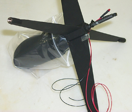
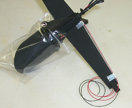
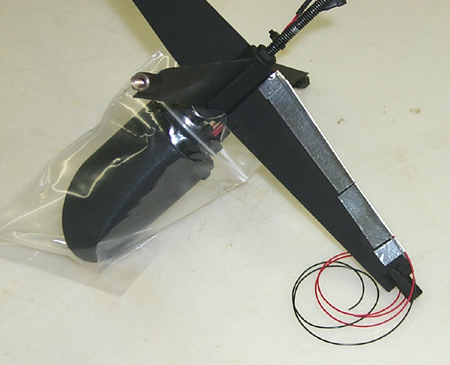
Following the instructions, attach the DewGuard to the back of the secondary mirror and install in the holder. Plug the supplied 9V plug onto the DewGuard. Note: The fine wires attached to the supplied plug have been intentionally reversed in polarity. When two 9V plugs are connected, the polarity is reversed, this second reversal brings the polarity back to the usual red being positive and black being negative. Next, the positive and negative wires are run along the edge of the spider, minimizing diffraction. The DewGuard uses very little power, so the supplied 28 gauge wire is sufficient. Lay the wires on top each other along the top edge of the spider and hold with a piece of the aluminum tape about 1/4" wide x 1" long (see photo below, top left and center). Pull the wires straight and use another 1/4" x 1" piece to hold the wires near the end of the spider vane (photo top right). Use longer pieces of aluminum tape to hold the wires along the entire spider vane (center left photo). The tape can be touched up with flat black paint at this point.
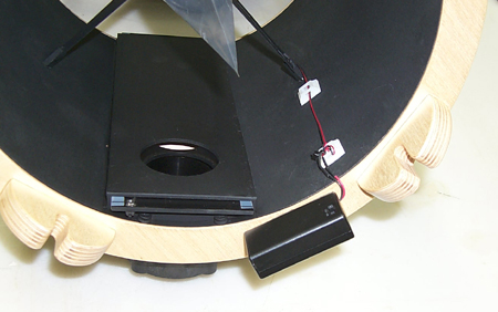
The wires are held on the inside of the tube or cage with adhesive backed wire mounts, which can also be screwed in place if preferred with the supplied screws (photo center right). This photo shows the battery box on the bottom of the cage, you can also drill a small hole in the baffle and mount the battery box on the outside of the cage (photo bottom left). Once you determine the battery box position, use the supplied Velcro to attach it. Last, attach the wires from the spider to the battery box, matching red to red and black to black. Slide a length of the heat shrink on each wire before twisting together. You can twist the wires and then solder, or just leave twisted if you don't have access to a soldering iron. Slide the heat shrink over the joint and use a match or lighter to briefly heat the tubing. It will shrink over the joint, making it secure and weather tight. Check the installation by installing the battery and switching on. The indicator LED on the pigtail will glow dimly when powered and by holding the air temperature sensor, the DewGuard will come on and the LED will glow brightly.
For extreme dew conditions the wires from the spider can be connected with a plug at the cage and run down either the inside or outside of a truss to a high capacity rechargeable battery in the mirror box or rocker box. It is advisable to put a switch and a fuse (1A) in line with the DewGuard with this installation. The DewGuard consumes about 0.02 watt at 12V while connected to a power source to operate the temperature sensor. While this is small, do not leave the DewGuard powered, it will eventually drain a battery.
 |
 |
 |
 |
 |
Note: The indicator LED will only light when the temperature conditions activate the DewGuard. The LED will not light (but glow dimly) when power is applied if the secondary mirror is above the air temperature.
The DewGuard senses both the ambient temperature and the secondary temperature using two sensors: one on the circuit board and one on the pigtail. It compares the two and applies power to the heaters when the glass to air difference is less than or equal to the preset value. A small LED indicates power consumption and is at low brightness when there is a 2 degree or smaller difference between the air and glass. When the difference is greater than the preset, the unit switches on and heats the secondary. The LED will illuminate at full brightness when on. The adjustable potentiometer is preset at the factory with heat being applied when the secondary mirror is 1 - 3 degrees C above air temperature. A small screwdriver can be used if adjustment is necessary.
Using a small temperature difference preset will cause the unit to turn on sooner and may be used for the most severe conditions. A large temperature difference preset will allow the mirror to nearly reach air temperature before turning on, the preferred setting for typical dew or frost conditions. This will give the longest battery life and have a negligible effect on the optical figure of the secondary mirror while avoiding tube currents. The unit will remain off until the secondary mirror reaches the preset air/glass setting, then cycles on and off as the secondary mirror is gently heated.
We have found that the factory setting of 1-3 degrees C above air temperature has been sufficient for virtually all applications to date. We suggest that you first try the DewGuard at the factory setting before adjustments are made. If adjustment is necessary, the potentiometer is a 3/4 turn, so small changes are all that is needed.
DewGuard 1 (Small) -- turn potentiometer counter clockwise to increase heat
DewGuard 2 (Medium) -- turn potentiometer counter clockwise to increase heat
DewGuard 3 (Large) -- turn potentiometer clockwise to increase heat.
Temperature control + or - 15 degrees C
Operating range 12 volts DC nominal, (6-18 volts will work)
Reverse polarity protected
| DG-1 | DG-2 | DG-3 | |
| Secondary Size | 1.5" - 2.5" | 2.6" - 3.1" | 3.5"- 7.0" |
| Power | 2W max. | 3W max. | 4W max. |
| Current (A@12V) | 0.2 | 0.3 | 0.4 |
| Heating Elements | 4 | 6 | 8 |
| Circuit Board Dimension - minor axis | 1.25" | 2.25" | 3.2" |
| Circuit Board Dimension - major axis | 1.8" | 3.1" | 4.6" |
The secondary mirror size is based on the minor axis, or width. The secondary holders manufactured by AstroSystems will accommodate a secondary mirror that is within 1% of the nominal holder size. It is also required that the mirror have an accurate proportion between minor and major axis dimensions. While it appears that the slit in the side of the shroud would allow it to fit varying mirrors, the forming of a rigid lip limits the adjustability to 1% variance in size.